Microwave nondestructive testing
Page 1 : Microwave NDT
Page 2 : Experimental set-up
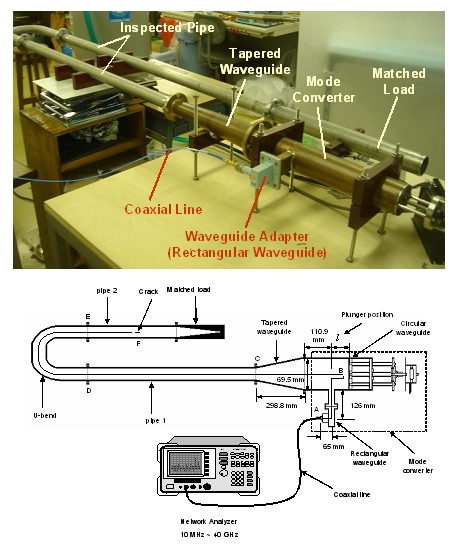
Experimental set-up
We are using the following experimental setup for this research.
The system consists of vector network analyzer, mode converter, tapered waveguide,
inspected pipe and matched load.
The network analyzer can generate microwave.
Microwave enter the mode converter.
Then mode of the microwave is converted from rectangular TE10 mode to circular mode.
Microwave is propagated to inspected pipe through the tapered wave guide.
Then the microwave is reflected at the crack and return to network analyzer.
At that time network analyzer get signal of microwave.
Microwave transmitted at the crack is absorbed in the matched load.
We can replace the matched load to the mode converter to obtain information of transmitted wave.
 |
| Experimental set-up |
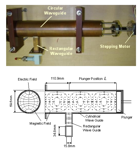 |
| Mode converter |
Experimental results
We evaluated scattering parameter for detection of some defects.
In our experiments, we get scattering parameter in the inspected pipe without defects at first.
Then, we get scattering parameter in the inspected pipe with defects.
Then we calculate deference of the two scattering parameter.
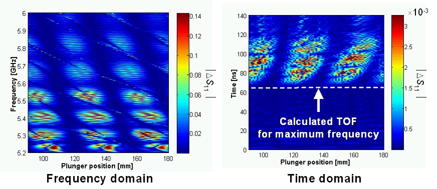
The following figures show examples of results when we applied the microwave NDT to
a longitudinal crack existing in straight pipe after U-bend.
Left graph is frequency domain data.
Horizontal axis indicates plunger position in the mode converter, from 90mm to 180mm.
Vertical axis indicates Frequency, from 5.2GHz to 6.0GHz.
Difference of scattering parameter, ΔS11, is shown as color gradation.
From the graph, ΔS11 in a certain plunger position.
In this region circular TE11 mode is resonated.
Right graph shows time domain data.
Horizontal axis indicates plunger position and vertical axis indicates time.
This time means how long microwave passes from network analyzer to crack and return from
crack to network analyzer.
The white line means calculated TOF for maximum frequency.
This is calculated by group velocity and real crack position.
This time domain data shows that ΔS11 appears at a certain plunger position
where circular TE11 mode is resonated.
And time when ΔS11 starts to appear almost agrees with calculated TOF.
This result shows we can predict longitudinal crack position with microwave NDT.
 |
| Experimental results |
hashizume-stafflovehashizume@grp.tohoku.ac.jp
Copyright © Hashizume & Ito & Ebara & Cheng Lab., All Rights Reserved.