Remountable high temperature superconducting magnet
Page 1 : Remountable HTS magnet
Page 2 : Mechanical joint of a HTS conductor
Page 3 : Heat transfer enhancement of LN2 with metal porous media
Page 4 : Other superconducting applications
Page 5 : Published papers
Mechanical joints of a HTS conductor
We have been investigated two mechanical joint methods of a HTS conductor;
Mechanical lap joint and mechanical butt joint.
- Mechanical Lap Joint
- We can obtain broad contact area by increasing in overlapped area.
- Current flows in the direction of c-axis at the joint region.
- Current flows through a stabilizer layer at the joint region.
- Mechanical Butt Joint (Mechanical Scarf Joint)
- We can't obtain broad contact area.
- Current flows in the direction of ab-plane at the joint region.
- Current flows from HTS filament to HTS filament directly.
Surfaces of HTS tapes or HTS conductors are jointed mechanically with a perpendicular joint force. This method has the following characteristics.
 |
| Mechanical Lap Joint |
Cross-sections of HTS tapes or HTS conductors are jointed mechanically. A direction of joint force depends on contact surface's shape. This method has the following characteristics.
 |
| Mechanical Butt Joint |
Test conductor
We are using BSCCO 2223 conductors as test conductors.
So far, we are investigating the mechanical butt joint of the BSCCO 2223 conductor mainly.
Since our first target is a feasibility demonstration of the design by proving robustness
against heat generation at the joint parts, we have used a BSCCO 2223 tape as a test material
although it is not available under a large magnetic field in a fusion reactor
due to degradation of its performance.
Recently, some companies are starting to sell YBCO 123 coated conductor.
So, now we also plan to use YBCO 123 coated conductor for our test conductor.
The following figures show test conductors that we used for mechanical butt joint.
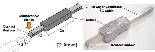
Stacked BSCCO 2223 conductor bundled with low temperature solder
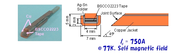
Stacked BSCCO 2223 conductor with copper jacket (1)
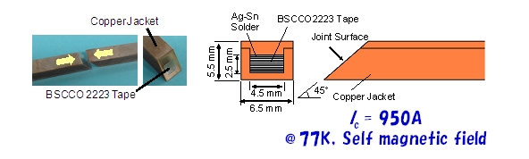
Stacked BSCCO 2223 conductor with copper jacket (2)
Experimental set-up
We are using experimental apparatus that can giving joint force to the test conductors.
(Please see the following picture.)
Joint stress is imposed by the rod above the center of the test cable.
The position of the rod is controlled through rotating the handle above the rod.
The joint stress is measured through the load cell located between the handle and the rod.
Voltage drop between the voltage taps is measured to estimate joint resistance.
The test section is cooled by liquid nitrogen.
DC current source can apply up to 1000A to the test conductor.
 |  |
| Whole view of experimental set-up | |

Test section
Fabrication of a prototype of remountable HTS magnet
We fabricated a small prototype of remountable BSCCO 2223 solenoid coil in 2005.
This magnet consists of two parts; 5-layered BSCCO 2223 conductor (IC = 280A at 77K),
is fixed on two remountable coil bobbin.
There exists 4 joint region where mechanical butt joint is applied.
Joint force is obtained by thermal shrink of acrylic boards at the jointing region.
The prototype magnet generates 4.5mT at center of the bore when applied current is 280A.

Prototype of remountable BSCCO 2223 solenoid coil
In terms of results obtained in this study, please see our published papers.
hashizume-stafflovehashizume@grp.tohoku.ac.jp
Copyright © Hashizume & Ito & Ebara & Cheng Lab., All Rights Reserved.